[Vassilis Papanikolaou] took a good thing and made it better with some design upgrades to this AVR based signal generator. We looked at version 1.0 of this tool back in 2006 and since then it saw an upgrade to 2.0. But [Vassilis] wanted to take things one step further, with a compact single-sided PCB. What you see above is the beautiful result of his work; a professionally made board that is compact, uses through-hole components, and has zero wire jumpers.
If you want to build one for yourself there’s a great parts list as well as board artwork and schematic. The system uses an ATmega16 so you’ll need a way to program one. There’s also just a bit of firmware tweaking to remap the control buttons to match the updated hardware layout.
For want of new test equipment, or simply a project, [Enzo] decided he would take a shot at creating his own waveform generator*. Not only is it a great project, it’s also a decent piece of test equipment, with proper signal conditioning, a nice front panel, and a built-in wall transformer.
The guts of [Enzo]‘s waveform generator is an AD9833 programmable waveform generator, a neat little chip that can output square and triangle waves fro 0.1 Hz to 3.2 MHz and sine waves from 0.1 Hz to 1.6 MHz. [Enzo] is controlling this chip with a PIC16 microcontroller, with a whole bunch of analog circuitry between the digital domain and the BNC connector on the front panel.
The waveform generator is controlled by a suite of dials and switches on the front panel, giving [Enzo] complete control over his new tool.
[Herp] just shared a nice 1MHz Arbitrary Waveform Generator (right click -> translate to English as google translation links don’t work) with a well designed user interface. His platform is based around a PIC32, a TFT module with its touchscreen and the 75MHz AD9834 Direct Digital Synthesizer (DDS). Of course the latter could generate signals with frequencies up to 37.5MHz… but that’s only if two output points are good enough for you.
As you can see in the video embedded below, the ‘tiny dds’ can generate many different kinds of periodic signals and even ones that are directly drawn on the touchscreen. The offset and signal amplitude can be adjusted using several operational amplifiers after the DDS ouput and a separate SMA TTL output is available to use a PIC32 PWM signal. The platform can read WAV audio files stored on microSD cards and also has an analog input for signal monitoring. Follow us after the break for the video.
[Bill Meara] of the Soldersmoke Podcast has a nice old Drake 2B radio, and wanted to use it for the 12 meter amateur band. These old radios normally make switching tuning bands easy — you just swap out one frequency crystal for another and you’re set.
Only [Bill] didn’t have the 21 MHz crystal that he needed. No problem, because he had a junk crystal, a hacksaw, and a modern direct-digital synthesis (DDS) chip sitting around. So he takes the donor crystal, cuts it open, and solders the two wires directly from the DDS to the crystal’s pins. Now he’s got a plug-in replacement digital oscillator that doesn’t require modifying the nice old Drake receiver at all. A sweet little trick.
The video’s a little bit long, but the money shot comes in around 5:00.
Now, one might worry about simply plugging a powered circuit (the DDS) in place of a passive element (the crystal), but it seems to work and the proof of the pudding is in the tasting. We wonder how far this digitally-controlled-analog-receiver idea could be extended.
One of the acronyms you may hear thrown around is DDS which stands for Direct Digital Synthesis. DDS can be as simple as taking a digital value — a collection of ones and zeroes — and processing it through a Digital to Analog Converter (DAC) circuit. For example, if the digital source is the output of a counter that counts up to a maximum value and resets then the output of the DAC would be a ramp (analog signal) that increases in voltage until it resets back to its starting voltage.
This concept can be very useful for creating signals for use in a project or as a poor-man’s version of a signal or function generator. With this in mind I set out here to demonstrate some basic waveforms using programmable logic for flexibility, and a small collection of resistors to act as a cheap DAC. In the end I will also demonstrate an off-the-shelf and inexpensive DDS chip that can be used with any of the popular micro-controller boards available that support SPI serial communication.
All of the topics covered in the video are also discussed further after the break.
DDS Demo Hardware
I chose to use Programmable Logic (PL) to build the various circuits as it was quick to configure and didn’t require very much construction while being extremely flexible. It also didn’t require any software programming, IDE, target processor board, etc. This might be an interesting project for you if you are interested in learning or exercising some basic Programmable Logic skills, here I use Altera’s free Quartus II Web version and an inexpensive programmer clone. For the first couple of examples I am using a Complex Programmable Logic Device. (CPLD)
Basic Signal Generation
Altera CPLD DDS
Creating waveforms can also be done with dedicated logic, for example a CD4060 oscillator/counter can be used instead of the PL counter or also a microcontroller with I/O ports could be used. Note that the microcontroller version does better the more assistance it gets from dedicated peripherals such as a timer or a timer/counter that reloads without waiting for the processor to respond and reset it.
Here are two waveforms created with a simple counter and resistors organized as an R/2R ladder. As the output of the counter increments in binary, the resulting voltage divider created by the interconnected resistors and outputs creates consistent steps between each of the counts; 256 in this case due to 8 outputs being used. Taking the most significant bit also demonstrates a symmetrical square wave.
Building Different Signals is Easy
If the counter were to count downwards upon reaching its maximum count instead of resetting to zero, then a triangle waveform would be generated. So far that’s three waveforms using just a counter and some resistors.
On a slightly different topic, using just some I/O lines, an R/2R ladder, and an analog comparator (ala LM339) a basic type of Analog to Digital Converter (ADC) can be made. Don’t misread this, we were talking about going from digital to analog before but now we’re talking about going from analog to digital.
To describe it simply, a processor or digital counter is connected to the R/2R ladder which is connected to the input of an analog comparator. The voltage to be measured is then connected to the other input of the comparator and then the counter proceeds to count up until the R/2R ladder voltage equals or exceeds the voltage being measured. At that time the comparator trips and the equivalent digital value of the analog voltage being measured is represented by the counter value feeding the R/2R ladder.
Assuming that the voltage to be measured is somewhat stable, the process can be repeated to track the voltage as it (slowly) changes or the count can be reversed until the comparator clears and then reverses. This might be useful for measurements such as monitoring a battery voltage level, etc.
While continuing the use of an adjunctive comparator, a simple voltage to frequency converter can be made by having the counter change directions when the comparator trips. This is not a perfect converter (nothing I do is perfect, life and engineering is a compromise) as very notably the amplitude of the triangle waveform changes in amplitude, but a full voltage square wave would be easy to generate.
Basic Principles for Sine Wave Generation
DDS Sinewave
Finally we can create a sinewave through the addition of a look-up-table that contains the appropriate data to approximate a mathematical sine function. A look-up-table (LUT) is simply a piece of memory such as Read Only Memory (ROM) in series with the data, in our case the incrementing counter represents an incrementing address, and the data output is the result of a pre-calculated Sine table.
For this I have switched to a Field Programmable Gate Array (FPGA) which has better internal memory and the ability to initialize the memory with the contents of the Sine table I created for the LUT. In the schematic for the interior of my FPGA the LUT can be seen off to the right just in front of the output pins.
FPGA w LUT
Programming Complex Waveforms
One advantage of a Sine wave created by DDS is that it can be generated at a wide range of frequencies and keep its same shape (low distortion).
Just for fun and to demonstrate something that can done easily with DDS I created a non-symmetrical waveform. Looking carefully you can see two cycles of square wave, two of ramp and then two of sine wave. Any waveform that can be “drawn” in memory can be created this way.
Square-ramp-sine
Other DDS Hardware Options
And finally, if you need a DDS without the muss and fuss of making it out of components yourself, there is a selection of DDS components available that are low cost and accurate. Shown here is an Analog Devices 9387 in an evaluation board from the manufacturer. It is SPI serial interface driven and so can be connected to most available single board controllers.
DDS Eval AD9837
Varying the frequency and phase of a signal by microprocessor control is integral to a DDS system. The software that comes with the evaluation the board shows that two frequencies and two phase offsets can be stored allowing Frequency Shift Keying (FSK) and Phase Shift Keying (PSK) as well as sweeping between two frequencies. This is a useful capability, for example the frequency response of a circuit such as a filter can be observed by sweeping a frequency on the input and then measuring the output on an oscilloscope.
Eval 9837
Go Deeper
If you want to know more about DDS there is a lot of information available on manufacturer’s websites and the Internet. Advanced topics to search for include embedded sub-modulation and use with phase lock loops to reduce phase noise, up-conversion using multipliers, and other synthesis circuits used in RF telecommunications.
In this installment of Scope Noob I’m working with Direct Digital Synthesis using a microcontroller. I was pleasantly surprised by some of the quirks which I discovered during this process. Most notably, I had a chance to look at errant triggers solved by using holdoff and a few timing peculiarities introduced by my use of the microcontroller. Here’s a video synopsis but I’ll cover everything in-depth after the break.
Direct Digital Synthesis
DDS is a method of creating analog signals from a set of digital inputs. I was inspired to give it a try after watching [Bil Herd’s] post and video on DDS. But he was using programmable logic and I thought I’d give it a try with a microcontroller.
R/2R Ladder
A simple R/2R Ladder is the key to this experiment. It’s a network of resistors in a 1:2 ratio with one another. I would recommend targeting 10k and 20k resistors; what I had handy was 500 and 1k which worked well for this. Eight bits of the microcontroller drive the digital inputs of the ladder, with a single output that is an analog voltage between 0V and Vcc.
My code examples for each of these experiments are available in this repository. The code was written for an ATmega328p (which is what the Trinket Pro is rockin’) but it’s vanilla enough to easily port for anything. My first run is a simple ramp signal using code that loops through an 8-bit variable and is also used as the output value. When it overflows the ramp begins again.
uint8_t counter = 0;
while(1) {
  PORTC = counter;
  PORTB = counter >> 6; //Shift the counter so MSB is on PB0 and PB1

  ++counter;
}
Notice that there are several yellow blips on that ramp signal. I’ll get into that in a little bit, but with a working “hello world” for the DDS I wanted to refine my methods by using hardware interrupts. Setting up Timer2 at the system clock rate of 16MHz with a counter resolution of 256bits still allows me to generate a frequency of 440 Hz:
It is worth noting that those blips in the signal are still there, just a bit harder to see on the above screenshot. As you can see, this signal is clocked at 438Hz, quite close to my target of 440Hz. That frequency is an ‘A’ in pitch. I figure I might morph this into an audio project eventually and if that happens I’ll wanted a signal that sounds better than a ramp wave does.
I Saw the Sine
This setup is well prepared for generating more interesting signals. All that’s needed is a better set of data to push to the ports than an incrementing counter. The most common way of doing this is to use a lookup table. I found a website that will generate sine wave values based on your parametric needs. I loaded up one with 256 bits of resolution so that I could still use the counter overflow as the index of the array.
ISR(TIMER2_COMPA_vect)
{
  static uint8_t counter = 0;       //Declare static this will only be instatiated the first time

  PORTC = sine[counter];            //Set PORTC
  PORTB = (sine[counter++]) >> 6;   //Set PORTB and increment the counter
}
That’s quite a pretty curve, but now we’re still seeing those signal anomalies and there’s a new issue. When I zoom in on the waveform I sometimes get a double signal. This looks like a sine wave inverted and overlaid on itself.
Not knowing what caused this I pinged [Adam Fabio] to see if he had any insights. He mentioned that it’s probably an issue of the scope triggering when it shouldn’t be.
The DS1054z that I’m using has two settings in the trigger menu that may be able to help with this. The first is a toggle that tells the scope to ignore noise when triggering. I was able to get this to work a little bit depending on my timebase and trigger voltage but it wasn’t a sure fix. The other option was Holdoff.
Learning about Holdoff
Holdoff is a feature that allows you to dial in a “blackout” window where the scope will not trigger. The best discussion of the feature that I found is [Dave Jones’] video regarding holdoff. He shows several use cases but mine is one of the easiest. I know the timing that my signal uses and I calculated that a holdoff just a bit longer than 2.1ms should be enough for the scope to trigger at the start of each period.
Splitting Microcontroller Ports
It’s finally time to figure out what’s going on with those blips in the signal. Here you can see that I’m measuring one of those blips which is about 1.024 us wide. That’s actually quite a lot and so I started probing around with channel two to see what’s going on. Very quickly I figured out that the blips always occur between bit 5 and bit 6 of the R/2R ladder.
In this case I’m really glad I used the Trinket Pro because otherwise I wouldn’t have had these blips to play around with. Normally I would use all eight bits on a single port but this board doesn’t offer that. Because of this I’m using PC0-PC5 and PB0-PB1. The blip occurs because of latency between writing PORTC and writing PORTB.
The C code that I wrote in the Interrupt Service Routine is very concise and beautiful C code. But the assembly generated from it shows why I’m getting large blips:
You can see that there are numerous instructions between the write to PORTC and the subsequent write to PORTB. This was simple to trace down because of my probing using the scope. The best part is that you don’t have to resort to writing your own assembly, instead you can just craft your C code with timing in mind:
In the interest of brevity, here is the resulting assembly and the new blip measurement (click to enlarge):
The result of coding with the microcontroller in mind shortens the blip in the signal by about 5 times! It is perhaps possible to further reduce this by half by using in-line assembly as there is still one instruction call in between port writes. But I think this a fantastic example of an oscilloscope saving you time in troubleshooting.
A Rant about Microcontroller Choice
Obviously working with a bare chip rather than a breakout board would have allowed me to use 8-bits on one port. But lets assume you were required to work with this restriction. With most 8-bit controllers you’ll hit another gotcha that I experienced here: to write to PORTB using one instruction I have to blow out the entire PORTB register even though I’m only writing 2 bits.
The reason for this is that you cannot write both digital 1 and digital 0 to the port using bitwise instructions. The best you could do is to first set your target bits to a known value, then to use a second instruction to write the bitwise values you seek. Obviously if you’re dealing with timing this is not optimal.
Most 32-bit microcontrollers (and some 8 or 16 bit varieties) have a workaround for this. Above is a paragraph from the TI datasheet for a TM4C123 chip. It shows that this processor allows single-instruction write without overwriting the entire port because it has a mask feature in the upper bits of the register. You can use an assignment operator and only the bits set in the mask register will be affected.
Homework
I don’t have a firm plan yet for next week so I can’t tip you off about the topic. Help me along by suggesting an area for me to explore by leaving a comment below.
If you are a hacker, you might consider ham radio operators as innovative. Most people, however, just see them as cheap. So it is no surprise that hams like [jmharvey] will build an antenna analyzer from a DDS module and an Arduino instead of dropping a few hundred dollars on a commercial unit. As he points out, you probably only need an analyzer for a day or two while you set up an antenna. Unless you are a big time antenna builder, the unit will then sit idle on the shelf (or will wind up on loan to hams even cheaper than you are).
The design is rooted in another proven design, but changed to take advantage of parts he happened to have on hand. Although the build is on a universal circuit board, [jmharvey] used Eagle to lay out the circuit as though it were a PCB. Since placement can be important with an RF circuit, this isn’t a bad idea. It’s always easier to move stuff around on the screen than on the perf board.
Since this is a no frills, unit, you are expected to grab the output from the Arduino and manually put it in a spreadsheet to plot the results. There is another version of the Arduino code that drives an OLED screen, although you still need a PC to kick the process off. One interesting feature of the Arduino code is how it deals with the nonlinear nature of the diodes used in the circuit. After plotting the values with known loads, [jmharvey] broke the diode operation into three regions and used different equations for each region. Even so, he warns that readings higher than 1:1 VSWR are only accurate to 10% or 20% – still good enough for ham shack use.
If you want an antenna analyzer for $40 (or less, if you have a good stock of parts) this looks like a worthwhile project. If, however, you want to repurpose it to Rickroll your neighbor’s AM radio, you might want to go with the commercial unit.
Click past the break to see the analyzer in action.
Hackaday reader [Jan Ostman] has been making microcontroller-based DIY synthesizers for quite a while now. Recently, he’s opened up the source for a lot of them so that you can play along at home. All of these virtual-analog synths and soundmakers can be realized on an Arduino or AVR ATmega328 if you happen to have one lying around.
Extra parts like a keyboard, some pushbuttons, or some potentiometer knobs to twiddle won’t hurt if you’d like to make something more permanent or more obviously playable, like [Jan] does. On the other hand, if you’d just like to get your feet wet, I’ve tweaked his code to be more immediately plug-and-play. The code is straightforward enough that it’s a good learning platform. So let’s take a quick tour through three drum machines and a string synth, each of which you can build on a breadboard in just a few minutes.
To install on an Arduino UNO, fetch the zip file from this GitHub repository, and move each subfolder to your Arduino sketch directory. You’re ready to play along.
Simple Drum Machines
[Jan] has two sample-playback~based drum machines that he’s published the code for: the dsp-D8 with straight-ahead drum samples and the dsp-L8 loaded with Latin percussion. They’re essentially the same code base, but with different samples, so we’ll treat them together.
Working through [Jan]’s code inspired me to write up a longer article on DDS playback, so if you want to brush up on the fundamentals, you can head over there. The short version is that you can change the pitch of playback of a sample by using a counter that’s much larger than the number of data points you’re going to play.
[Jan]’s drum machines all use the AVR’s hardware pulse-width modulation (PWM) peripherals to play the samples back out. You could use something fancier, but this gets the job done with just an optional resistor and capacitor filter on the output, bringing the total parts count to three: Arduino, 1 KOhm resistor, and a decent-sized (0.1 uF?) capacitor. An interrupt service routine (ISR) periodically loads a new sample value into the PWM register, and the AVR’s peripheral hardware takes care of the rest.
One nice touch is the use of a circular buffer that holds the playback sample values until the ISR is ready for them. In the case of the drum machines, there’s not much math for the CPU to do — it just combines the samples from all of the different simultaneous voices — but in his more complicated modules this buffer allows the CPU to occasionally take more time to calculate a sample value than it would otherwise have between updates. It buys [Jan]’s code some breathing room and still allows it to make the sample-playback schedule without glitching.
[Jan] adds individual pitch control for each sample, which is great for live playing or tweaking, and you can watch him use them in his two videos: one for the dsp-D8 and another for the dsp-L8. Wiring up so many knobs is a breadboard-salad, though, so I’ve gone through the code for you with a fine-toothed chainsaw, and hacked off [Jan]’s button-and-knob interface and replaced it with the Arduino’s built-in serial I/O.
To play my version of [Jan]’s drum machines, each sample is mapped to a key in the home row: “asdfjkl;”. If you’ve got a proper serial terminal program that transmits each keystroke in real-time, you’ll be tapping out rhythms at 9600 baud in no time. Note that the Arduino IDE’s built-in terminal only sends the keystroke after you hit “enter” — this makes playing in tempo very difficult. (I use screen /dev/ttyACM0 9600 or the terminal that’s built-in with Python’s pyserial library myself. What do Windows folks use for a real-time terminal?)
If you haven’t already, download this zip file, move each sub-folder to your Arduino sketch directory, and connect an amplified speaker either directly to your Arduino’s pin 11 and ground, or include an RC filter. It’ll only take a second before you’re playing. When you want the full version with all the knobs, head on over to [Jan]’s site.
O2 Minipops
[Jan]’s O2 Minipops machine mimics an old-school rhythm box: the Korg mini pops 7. Whether this primitive drum machine is horribly cheesy or divinely kitschy is in the ear of the beholder, but it’s a classic that has been used all over. [Jan]’s named his after an epic album Oxygene by Jean-Michel Jarre. You’ll hear them starting around 1:40 into the clip. Jarre famously used to press multiple buttons on the Minipops, making more complex drum patterns by playing more than one at a time.
The nice thing about having your own Minipops in firmware is that you can add the features you want to it. Instead of having to mash down multiple plastic buttons live on stage like poor Mr. Jarre, you can just tweak the firmware to suit. Need longer patterns? You’ve got the RAM. Emphasis? Swing? Tap tempo? It’s all just a matter of a few lines of code.
The sound playback code is just like the simpler drum machines above, so we won’t have to cover that again. The only real addition is the sequencer, but that’s where the real magic lies. After all, what’s a drum machine without some beats? Because there are eight possible drum sounds, each beat is a byte and so four bars of 4/4 time is just sixteen bytes stored in memory. I broke the data out into its own header file O2_data.h, so have a look there for the pre-programmed rhythms, and feel free to modify them to suit your own needs.
In order to make the O2 Minipops immediately playable, I stripped out the potentiometer code again (sorry [Jan]!) and passed off control over the serial port. The “user interface” has five controls. Press j and k to switch between patterns and f and d to speed up or slow down. (They’re under your first two fingers in the home row.) The space bar starts and stops the drum machine.
Try switching between the patterns on the fly with j and k — it’s a surprisingly fun way to create your own, slightly less cheesy, patterns. You need to download this code and give it a try. Trust me.
[Jan]’s Solina is a “virtual analog” in the sense that it builds up sawtooth waveforms in the microcontroller’s RAM and then outputs the corresponding voltage through PWM. And that’s a good start for a string synthesizer, because a filtered sawtooth waveform is a good first stab at the sound put out by a violin, for example.
Solina — the clone
The secret to the sound of the string section of an orchestra (and to string synthesizers that mimic it) is that it’s a combination of many different bowed instruments all playing at once. No matter how precise the players, they’re each slightly differently tuned, and none of the strings are resonating exactly in phase. The Solina mimics this by detuning each oscillator, naturally, and by moving them in and out of phase with each other. If you want to dig into the details of how exactly [Jan]’s Solina works, he explains it well in this blog post.
Again, I’ve converted it for direct-serial control, and you can control the envelope, detune, LFO speed, and modulation depth over the serial port. Press the spacebar once to simulate a keypress, and again to let go. Try the Solina with detune and pitch modulation around twenty, and play with the LFO rate and other parameters. That’s a lot of useful noise for just some sawtooth waves.
Keyboards and What’s Next
[Jan]’s builds are much more than what we’re demonstrating here, of course. His blog kicks off (in 2009!) with a project that essentially shoe-horns a PC into a keyboard enclosure, and the Solina and others get their own keys too. We’ve just presented the kernel of any such project — there’s a lot of labor-of-love left in wiring up all of the diodes necessary to do detection on a keyboard matrix, to say nothing of building enclosures, wiring up potentiometers, and making nice-looking front panels. But if you want to start down that path, you’ve at least got a good start.
[Jan]’s current project is the Minimo miniature monophonic synth that takes the Solina a step further and adds a lowpass filter with (digital) resonance to it. The resulting sounds are great, so we’re excited to see where [Jan] takes this one in the future.
Thanks again, [Jan], for opening the code up. And if any of you build something with this, be sure to post in the comments and let us all know. Since I started playing around with these, I’ve got the hankering to modularize the code up a bit and make it into something that’s even easier to adapt and modify. Maybe we’ll have to start up a Hackaday.io project — these little simple synths are just too much fun!
What do you get when you combine a direct digital synthesis (DDS) chip, a power detector, and an Arduino? [Brett Killion] did make that combination and wound up with a practical network analyzer.
The project uses an Analog Devices AD9851 DDS chip clocked at 180 MHz which will output a sine wave at any frequency from 0 Hz and 72 MHz. A Butterworth low pass filter processes the DDS signal and then feeds a two-transistor amplifier. The circuit will output about 0dBm into 50 ohms. The power detector is an Analog Devices AD8307 along with a 50-ohm input load. There is no filtering on the power detector so it can measure from very low frequencies to 500MHz.
[Brett] uses a Python program to process the data from the Arduino. For example, here’s a plot of a 10 MHz crystal from the software:
If you want to know more about DDS, our own [Bil Herd] has you covered (see the video, below). We’ve also seen similar antenna analyzers that are about the same thing.
There’s a lot more to learning how to play the guitar than just playing the right notes at the right time and in the right order. To produce any sound at all requires learning how to do completely different things with your hands simultaneously, unless maybe you’re a direct descendant of Eddie Van Halen and thus born to do hammer ons. There’s a bunch of other stuff that comes with the territory, like stringing the thing, tuning it, and storing it properly, all of which can be frustrating and discouraging to new players. Add in the calluses, and it’s no wonder people like Guitar Hero so much.
In an interesting departure from standard stringed instrument construction, plucking is isolated from fretting. The player fingers notes on four strings but plucks a special, fifth string with a conductive pick that closes the plucking circuit. By contrast, the fretting strings are normally high. When pressed, they contact the foil-covered fingerboard and the circuit goes low. All five strings are made of carbon-impregnated elastic and wrapped with 30AWG copper wire.
All five strings connect to an Arduino UNO and then a laptop. The laptop sends the signal to a Bluefruit friend to change Bluetooth to UART in order to satisfy the PIC32. From there, it goes out via 2-channel DAC to a pair of PC speakers. One channel has the string tones, which are generated by Karplus-Strong. To fill out the sound, the other DAC channel carries undertones for each note, which are produced by sine tables and direct digital synthesis. There’s no cover charge; just click past the break to check it out.
It’s easy to have a soft spot for “mini” yet perfectly functional versions of electronic workbench tools, like [David Johnson-Davies]’s Tiny Function Generator which uses an ATtiny85 to generate different waveforms at up to 5 kHz. It’s complete with a small OLED display to show the waveform and frequency selected. One of the reasons projects like this are great is not only because they tend to show off some software, but because they are great examples of the kind of fantastic possibilities that are open to anyone who wants to develop an idea. For example, it wasn’t all that long ago that OLEDs were exotic beasts. Today, they’re available off the shelf with simple interfaces and sample code.
The Tiny Function Generator uses a method called DDS (Direct Digital Synthesis) on an ATtiny85 microcontroller, which [David] wrote up in an earlier post of his about waveform generation on an ATtiny85. With a few extra components like a rotary encoder and OLED display, the Tiny Function Generator fits on a small breadboard. He goes into detail regarding the waveform generation as well as making big text on the small OLED and reading the rotary encoder reliably. His schematic and source code are both available from his site.
Small but functional microcontroller-based electronic equipment are nifty projects, and other examples include the xprotolab and the AVR-based Transistor Tester (which as a project has evolved into a general purpose part identifier.)
I don’t have a signal generator, or more specifically I don’t have a low frequency signal generator or a function generator. Recently this fact collided with my innocent pleasure in buying cheap stuff of sometimes questionable quality. A quick search of your favourite e-commerce site and vendor of voice-controlled internet appliances turned up an FG-100 low frequency 1Hz to 500kHz DDS function generator for only £15 ($21), what was not to like? I was sold, so placed my order and eagerly awaited the instrument’s arrival.
The missing function generator is a gap in the array of electronic test instruments on my bench, and it’s one that maybe isn’t as common a device as it once might have been. My RF needs are served by a venerable Advance signal generator from the 1960s, a lucky find years ago in the back room of Stewart of Reading, but at the bottom end of the spectrum my capabilities are meagre. So why do I need another bench tool?
It’s worth explaining what these devices are, and what their capabilities should be. In simple terms they create a variety of waveforms at a frequency and amplitude defined by their user. In general something described as a signal generator will only produce one waveform such as a sine or a square wave, while a function generator will produce a variety such as sine, square, and sawtooth waves. More accomplished function generators will also allow the production of arbitrary waveforms defined by the user. It is important that these instruments have some level of calibration both in terms of their frequency and the amplitude of their output. It is normal for the output to range from a small fraction of a volt to several volts. How would the FG-100 meet these requirements? Onward to my review of this curiously inexpensive offering.
Noisy as Sin
The package duly arrived, and inside was the unit itself with no power supply or instructions. It is well-presented in an ABS enclosure a little bigger than a pack of cards with a custom front panel for the buttons, LCD, a BNC output, plus a knob for the amplitude on the right hand side. On the left hand side is a power jack to supply the required 5 volts. Handily the jack is the same size and polarity as the one used on older 5 volt Nokia phones, so a rummage through the wall wart box yielded a suitable adapter. I’d have expected the ubiquitous micro-USB in 2018, or at least a USB-to-power-jack cable, but sadly neither were present.
A few transients showing on the 1kHz sine wave.
Upon power-up, the display lit up with “Wave: Sine” and “Freq: 100000”, and a flashing cursor in the frequency display. There are two modes to the interface, this one in which the waveform can be set, and another in which they are locked while the generator is running. There is a “Run/stop” button to toggle between the two and enable the output, a “Mode” button to select between sine, square, triangle, sawtooth, and reverse sawtooth waveforms, and a mildly inconvenient three-button interface to select frequency. There is also a switchable filter and a switchable DC offset facility. Unfortunately it has no capacity to remember the last settings used, so it will always start with 100kHz.
Evaluating a signal generator is an exercise largely performed with an oscilloscope, in that a modern ‘scope also contains the functions of a frequency counter and through its FFT capability, a rudimentary spectrum analyser. The FG-100 was hooked up to the trusty Rigol, and it’s worth saying that a variety of different termination resistors were used in these tests and were found to make little difference to their outcomes.
This is a low-frequency generator, so on first activation it was set to 1kHz. There were some visible transients on the waveforms, whichever type was selected. The amplitude was variable from 0 to 24 volts peak-to-peak, and if the DC offset feature was enabled the waveform could be shifted from about -10V to +10V. There is no calibration of any sort upon either offset or amplitude, but all frequencies measured were what the generator claimed it was producing.
At 10kHz that’s not a sine, it’s a sin!
As the frequency was increased there appeared visible distortion on the sine waveform, starting above about 5kHz and becoming really pronounced from 10kHz upwards. Looking at the waveform it is similar in appearance to crossover distortion on a poorly designed class B amplifier, though it is seemingly not subject to such treatment. The distortion increases to the point at which all types of supported waveform approximate to a triangle at 50kHz, after which the amplitude tails off.
Measuring the low frequency square wave rise time at a pedestrian 25μS backs up this discovery, it is evident that this is no 500kHz device. Stepping through the frequency range it produces a detectable signal of some sort all the way up to the 999.999kHz maximum on its interface, but it is pretty evident that its usable bandwidth is only below 50kHz.
Well designed, but let down by poor components?
Inside the FG-100, and despite its performance shortcomings it’s a physically well-designed piece of kit.
On the back of the enclosure are four screws, these are long M3 threaded bolts that screw directly into the ABS, they are not the expected self-tappers. Removing the lid reveals the FG-100’s secret, there is no dedicated DDS chip at all but an ATMega328 in a socket at its heart. Other components are what looks like a resistor ladder DAC, a switching power supply chip, a couple of TL072 op-amps for signal conditioning, and an HD4480 clone LCD display that is also socketed. The switches did not seem to be of especially poor quality, and each one had a plastic cap for the front panel.
Conclusion
So given my investigation of the FG-100, what’s the verdict? It’s fairly obvious that I bought it mostly in the continuance of my occasional series of reviews of cheap stuff rather than in the expectation of a high quality instrument, and it’s thus fair to say that it will not join my bench as my everyday function generator. It’s no diamond in the rough, though it’s technically using DDS to create waveforms it has no dedicated DDS chip, its waveforms exhibit distortion and transients, its bandwidth is nowhere near that advertised, and it has no amplitude calibration whatsoever.
It’s a pity because its construction shows some attention to physical design detail, but I can’t honestly recommend that anyone add one to their arsenal of test gear. For your £15 you get an Arduino in a box with a display and a load of buttons, along with a bit of questionable signal conditioning circuitry. Assuming that its designer did originally create a half-decent low-frequency function generator I can only conclude that it has been let down by poor quality or counterfeit components in its analogue section, perhaps at some point I’ll try reverse engineering it to find what’s up. A quick look online finds most other suppliers carrying them for a bit more than what I paid, so perhaps I even got suckered with some kind of knock-off.
You’re probably asking why anyone would have expected more for such a small outlay and you’d be absolutely right, but then again if you’ve followed my reviews in this vein you’ll be aware of the joy to be found in poking into poor quality hardware. It’ll join the comical multimeter and the disintegrating desoldering pump. But lest you think all £15 purchases are junk you should take a look at the much better temperature controlled soldering iron and pocket oscilloscope.
Although there are a few exceptions, FPGAs are predominantly digital devices. However, many FPGA applications process analog data, so you often see an FPGA surrounded by analog and digital converters. This is so common that Opal Kelly — a producer of FPGA tools — launched the SYZYGY open standard for interconnecting devices like that. [Armeen] — a summer intern at Opal Kelly — did a very interesting open source FPGA-based signal generator using a Xilinx FPGA, and a SYZYGY-compliant digital to analog converter.
As you might expect, [Armeen] used a lot of Opal Kelly hardware and software in the project. But the Verilog code (available on GitHub) shows a lot of interesting things including some very practical example code for using Xilinx CORDIC IP, which is a great way to do high-order math using digital logic.
Following how the AM and FM generation works is a great introduction to signal synthesis in an FPGA. If you don’t want to use the Xilinx IP, you can find several CORDIC cores on OpenCores. Overall, this is a pretty good intermediate project if you are trying to get your head around FPGAs. It is complex enough to show you something practical but not so complex that you’ll get frustrated. Of course, a lot of the functions are wrapped up in the Xilinx IP which you can think of as being akin to using a C or Java library.
SYZYGY is a specification that is free to license, by the way. It is supposed to bridge the gap between simple PMODs and high-speed FMC boards. There’s even an open source platform board to support it. However, as far as we know, only Opal Kelly currently ships any plugins for it, so it remains to be seen how popular or unpopular it may prove.
Somehow [hvde] wound up with a CB radio that does AM and SSB on the 11 meter band. The problem was that the radio isn’t legal where he lives. So he decided to change the radio over to work on the 6 meter band, instead.
We were a little surprised to hear this at first. Most radio circuits are tuned to pretty close tolerances and going from 27 MHz to 50 MHz seemed like quite a leap. The answer? An Arduino and a few other choice pieces of circuitry.
In particular, [hvde] removed much of the RF portion of the radio, leaving just the parts that dealt with the intermediate frequency at 7.8 MHz. Even the transmitter generates this frequency because it is easier to create an SSB signal at a fixed frequency. The Arduino drives a frequency synthesizer and an OLED display. A mixer combines the IF signal with the frequency the Arduino commands.
The radio had a “clarifier” which acts as a fine tuning control. With the new setup, the Arduino has to read this, also, and make small adjustments to the frequency. The RF circuits in the radio took some modifications, too. It is all documented, although we will admit this probably isn’t a project for the faint of heart.
[Steven Merrifield] built his own Scalar Network Analyzer and it’s a beauty! [Steve]’s SNA has a digital pinout matching a Raspberry Pi, but any GPIO could be used to operate the device and retrieve the data from the ADC. The design is based around a few tried and true chips from Analog Devices. He’s taken some care to design it to be nice and accurate which is why he’s limited it to 1kHz to 30Mhz. We think it’s quite a fetching board once the shielding is in place.
We’ve covered network analyzers and their usefulness before. If you want to know how, for example, a mystery capacitor from your junk bin will respond to certain frequencies, a network analyzer could tell you. We’ve even taken a stab at hacking together our own.
There is more documentation on his website as well as some additional example curves. The board is easily ordered from OSHpark and the source code is available for review.
A lifetime of amassing random pieces of test equipment has left me with a gap in my armoury, namely that I don’t possess a low frequency function generator. This could easily be addressed, but for two things. I have a love for exploring the cheaper end of exported electronics and my need for a function generator is less than my desire to spend significant cash. I’ve tried to balance these competing forces in the past by picking up an astoundingly cheap instrument; that time I ended up with a lemon, but will lightning strike twice in the same spot? I spent £10 ($13) on a different cheap function generator and set off to find out.
So Good, They Forgot To Name It
I could tell my DDS function generator was a quality product when I opened the anti-static bag it came in, for whoever manufactured it wasn’t prepared to put their name to it and it has no model number I can see. Hence I’ll refer to it as the Unnamed Chinese DDS Function Generator. Jokes aside, it seems to be of a generic type that can be found from a variety of the usual online stockists. It takes the form of a PCB about 100 mm by 80 mm with one of the ubiquitous alphanumeric display modules atop it, and a couple of BNC sockets for output. Control is via a set of momentary action buttons, and there are a couple of potentiometers for level and DC offset. Finally there is a 2.1 mm barrel jack through which it will accept 7 V to 9 V DC. Surprisingly the polarity of this is unlabelled, but a quick check of the electrolytic capacitor it’s connected to revealed the centre pin to be positive.
The previous cheap function generator had been an ATmega328 with a resistor ladder DAC, and it suffered from both huge distortion and inconsistent amplitude over its frequency range. I’m not expecting this one to be on a par with a four-figure-sum signal generator, but as long as it can deliver the waveform it claims and at the same amplitude and offset across its range then I’ll be happy with it. So my first order of business was to hook up the ‘scope and see how it handles delivering a sine wave.
The function generator is certainly more reliable than the USB screenshot feature on a Hantek ‘scope!
The good news is that this generator does exactly what it claims. From its 1 Hz lower end to its 65.5 kHz upper end, the sine wave shape remains the same and the amplitude and offset I selected on the two potentiometers is consistent. The other waveforms are the same, square, triangle, sawtooth, random noise, and unexpectedly, an ECG waveform that looks super realistic at 1 Hz with a 200 mS timebase. Is that in there for novelty film props? There is also a separate higher frequency square wave output that can deliver between 1 MHz and 8 MHz at logic levels.
So it’s a capable little function generator, but where is the bad news? As you’d expect from a £10 outlay it’s not quite a perfect function generator. At the higher frequencies its sample step becomes visible on the ‘scope, but most annoyingly in operation, the potentiometers lack a fine control. Getting an amplitude and offset right on the mark can be a frustrating process. Still neither of these come as a game over moment for such a cheap instrument, even with them it will suffice for my needs.
What Powers This Unexpectedly Useful Instrument?
Laid bare, the function generator’s chips.
Undoing the two screws to remove the LCD, and the device’s inner secrets are laid bare. At its heart is an ATmega16 with an R/2R resistor ladder DAC made with an array of 10 kΩ and 20 kΩ resistors, and following that is an NE5532 dual op-amp that presumably handles the amplitude and DC offset. Finally there is an ICL7660 switched-capacitor voltage doubler unexpectedly in a socketed DIP-8 package, at a guess to give enough DC overhead to provide the range of output voltages. Otherwise the only semiconductor is a 78L05 voltage regulator, making it a surprisingly simple device.
In conclusion then, should you spend your tenner on this function generator? Being honest, I splashed out on it half in the expectation of another entertainingly bad piece of junk to amuse you with, and was instead pleasantly surprised to receive a unit that works as expected and delivers exactly what I need from a cheap function generator. In that case it’s a definite diamond in the rough, and should you need an audio function generator and don’t mind a few shortcomings then you should certainly give it a look.
[JanHerman] knows that tuning musical instruments is all about precision and that precision is measured in a logarithmic unit called a cent. A cheap tuner unit might be accurate to 1.5 cents which sounds good until you look at one for ten times the price and find it is accurate to 0.1 cents. So you can spend $800 for precision or $60 for something less. [Jan] decided to build something better and cheaper using a 32-bit Arduino and a DDS frequency generator chip on a breakout board.
Oddly enough, the device doesn’t have a display. Instead, it generates a precise frequency and couples it to the piano using a transducer. You tune the string to the corresponding note. The post has a lot of detail about how piano tuning works.
If you know about the chromatic scale, the equal temperament system, and how many cents are in an octave, you might want to skip the first section. We didn’t though. If we learned any of that in childhood piano classes, we’ve forgotten it.
For those whose quest for precision isn’t that critical, note that the difference between two notes can be as little as 0.3316 Hz. It is interesting that the final design isn’t the first one [Jan] attempted and there is an explanation of why the first design wasn’t successful.
The final design calls for a 24-position rotary switch which is tough to find. We might have opted for a rotary encoder and a display or even some LEDs to make a cheap alternative. As it was, the cheap switch used caused problems and required a replacement and very careful soldering.
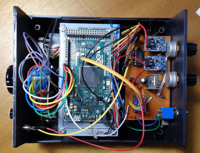
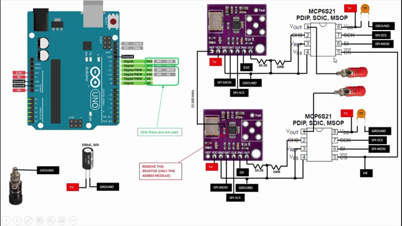
Microcontroller addict [Debraj] decided to make his own programmable sine wave generator, and was able to put it together for under $40 USD. Other than low-cost, his list of requirements was as follows:
Dual sine wave output, synchronized
Frequency, Amplitude, and Phase control
Low harmonics under 1 MHz
Scriptable via Python
The heart of the project is the Analog Devices AD9833, a complete Direct Digital Synthesis (DDS) waveform generator system on a chip. If you’ve ever rolled your own DDS using discrete ICs or in an FPGA, you can appreciate the benefit of squeezing the phase accumulator, sine lookup table, DAC, and control logic all into a single ten-pin package. [Debraj] uses AD9833 modules from the usual online vendors for a few dollars each. He synchronizes the generators by disconnecting the reference crystal on the second module and driving it from the first one. The remaining specifications are met by the inherent characteristics of the DDS system, and the scriptable interface is accomplished with an Arduino controlling the AD9833 chips and two programmable gain amplifiers (MCP6S31). We like the confidence that [Debraj] displays by sketching the initial circuit diagram with a ball-point pen — check out the sketch and the final pictorial schematic in the video below the break.
This is a good example of combining off-the-shelf modules to quickly build a project. This approach is great for one-off builds or as a proof-of-concept test bed that can later be spun onto a custom PCB. Another reason to use modules these days is that the modules are often in-stock but the chips are unobtainable. Though it appears [Debraj]’s only needs one of these generators, it would be an easy board to layout and build — if you can buy the parts.
In the ham radio trade, gear such as the old Drake units [Dr. Scott M. Baker] has in his radio shack are often referred to as “boat anchors.” It refers to big, heavy radios that were perhaps a bit overengineered compared to the state of the art at the time they were designed, and it’s actually a shame that the name has taken on something of a pejorative connotation, since some of this gear is rock solid half a century or more after it was built.
But older gear is often harder to use, at least compared to the newer radios with microcontrollers and more stable oscillators inside. To make his 1970s-era Drake “Twins” setup of separate but linked receiver and transmitter a little more fun to use, [Scott] came up with this neat Raspberry Pi-based DDS-VFO project to keep his boat anchors afloat. Compared to the original mechanically tuned variable frequency oscillator in the Drake receiver, the direct-digital synthesis method promises more stability, meaning less knob-nudging to stay on frequency.
The hardware used for the DDS-VFO is actually pretty simple — just a Raspberry Pi Zero W driving an AD9850-based signal-generator module. Sending the signal to the Twins was another matter. That was done by tapping into the injection cable linking both units, which meant a few circuit complications to deal with signal attenuation. [Scott] also added amenities like a digital frequency display, optical encoder with crank-style knob to change frequency, and a host of Cherry MX keyswitches for quick access to different features.
From the look of the video below, the Twins are now rock-solid and a lot easier to use. This project is loosely based on a recent panadapter project [Scott] undertook for the receiver side of the Twins.
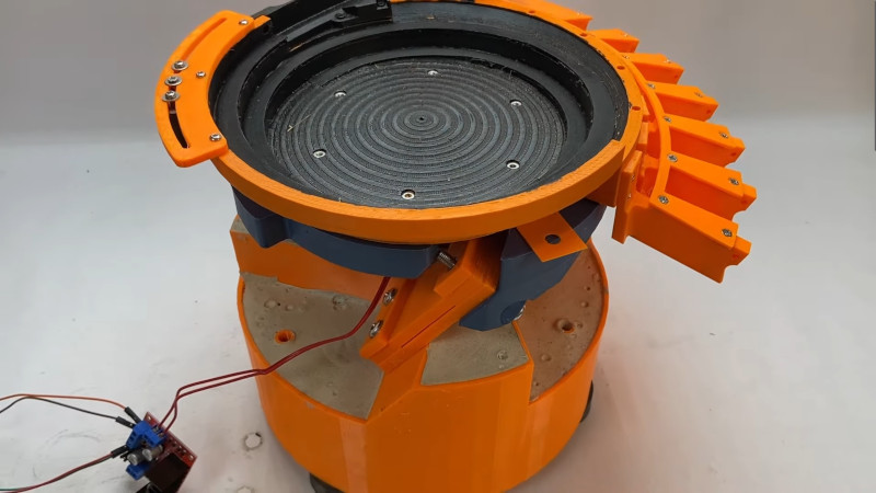
If you spend much time around industrial processes, you may have seen a vibrating bowl feeder at work. It’s a clever but simple machine that takes an unruly pile of screws or nuts and bolts, and delivers them in a line the correct way up. They do this by shaking the pile of fasteners in a specific way — a spiral motion which encourages them to work to the edge of the pile and align themselves on a spiral track which leads to a dispenser. It’s a machine [Fraens] has made from 3D printed parts, and as he explains in the video below the break, there’s more to this than meets the eye.
The basic form of the machine has a weighted base and an upper bowl on three angled springs. Between the two is an electromagnet, which provides the force for the vibration. The electromagnet needed to be driven with a sine wave which he makes with an Arduino and delivers as PWM via an H-bridge, but the meat of this project comes in balancing the force and frequency with the stiffness of the springs. He shows us the enormous pile of test prints made before the final result was achieved, and it’s a testament to the amount of work put into this project. The final sequence of a variety of objects making the march round the spiral is pure theatre, but we can see his evident satisfaction in a job well done.
Oddly this isn’t the first bowl feeder we’ve seen, though it may be one of the most accomplished. We particularly like this tiny example for SMD parts.